At the 15th annual NEIU Student Research and Creative Activities Symposium.
My research was to create and test a noise generator for testing Digital Filters.
I had never been to the Symposium and it was an amazingly fun time. I got to meet alot of outgoing and interesting people doing very fun stuff.
It was cool to see how people appreciated different aspects of the project depending on what their domain of expertise was.
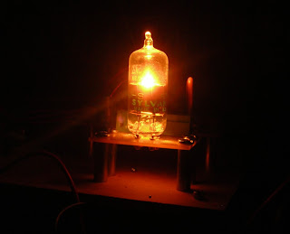
I got a few questions about use for noise generators in radio astronomy. That is definantly a use, this research paper on
Jovian emmissions used the same thermionic diode that was in one of the noise generators I worked on.
I also got a question about the amplification necessary. I skipped over that in my presentation, due to only having 15 minutes to talk, but it was a HUGE problem to amplify the noise enough to sample it (especially over a wide bandwith). I used THREE of the
Mini Circuits GVA-84+ amplifiers with around 24 dB of gain each, PLUS an
Analog Devices AD8351 amplifier with 26dB of gain. for a total of 98(!!!!) dB of gain. And this STILL didn't full scale my Analog to Digital Converter. (which had a negative effect on my FIPS tests, but I ran out of time to get more amplification before presenting).
The amplifiers have basically 4 components. Input blocking capacitor and and output blocking capacitor that have to be of very high quality (no parasitic inductance, high purity materials). There is an RF Choke working as a voltage pull up and it also has to be of high quality (no parasitic capacitance). The RFC is a fairly big piece of high permiability core with very little wire, to minimize group delay and parasitic capacitance. By using a large core, it stays away from saturation and still looks linear. If any of these aren't functioning near there theoretical limits, it will limit our bandwith. The last part is the amplifier itself, which is usually electrically simple, but employs very fancy physics for the transistors. The Mini Circuits amplifiers use an InGaP HBT technology, and the Analog Devices amp uses an "advanced silicon bipolar process."
I also got a question the FIPS tests. To go into a little more detail, the Monobit test asks: If our numbers resulted from flipping a coin, is the coin neutrally balanced?
The Poker test asks: Given our four bit chunks, Do we get equal distribution of the possible "hands."
The Short Runs test asks: Do our numbers correspond to our expected statistical distrobution? (I haven't calculated what type of distrobution the expect yet.)
The Long Runs tests: Do we have values OUTSIDE our expected distrobution.
All in all, it was very thrilling time.