Friday, March 23, 2007

Filament Power Control Installation.


The filament power control was mounted after the rheostat was tested for overheating.

Also created a Faraday cage to isolate the signal elemants from RF interference.

Wednesday, March 21, 2007

Filament power control

Installed Rheostat

Today my father and I went to an undisclosed location in the western part of the state, to buy this rheostat:


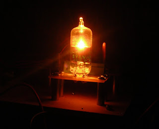
The rheostat is rated at 10 Ohms and 25 watts. In circuit this provided us with a current range across our filament from 0.5 to 1.4 Amperes. This is great since 1.6 amperes is the max current recommendation in the Sylvania datasheet.


Using a non-contact pyrometer we tested the rheostat knob for heating...

10:32 83 degrees (Room temperature for our third floor apartment with radiator heat!)

10:35 87 degrees.


This is fine, as Sylvania only recommends using the tube in five minute bursts.

While the rheostat is lossy in terms of power it has the benefit of adding only random noise, whereas a transistor under (op-amp) control could add noise from its feedback control system that could pollute our noise with causal signals.

I also installed a shielded tube socket without screw terminals for better signal quality. An ebay order came with tubes for a possible thermionic noise pre amp. They were previously used by silent key Billy G. Orock, Sr. (W7GSY) and I hope he approves of their new home.

Tuesday, March 20, 2007

RFCs


This is the filament RF Choke. This is a high current, low potential conduction path, is a 114A size toroid in 43 mix with 10 turns of 16 guage litzendraht wire. This measures at 110 microhenries


This is the plate RF Choke measuring at 1 milliHenry. It has very low current at very high potentials, and was purchased from surplus. Note the difference in windings, with very many turns of thin wire around an air core. Next to it is a .01uFd Silver Mica DC blocking capacitor. It is soviet military surplus and features high speed, low leakage and high stability.

Wednesday, March 14, 2007

Wow.


It's like a little sun in there.

Monday, March 12, 2007

More noise source work

DC Block and RF Choke from the noise tube to its SMA connector, as well as amplifier power.


The Red meter should show about 120 Volts from batteries for our high (Plate) voltage.
The Green meter will show the heater current. This is important to not burn out the tube and will be controlled by a Rheostat.
The Analog meter will show the Plate current.

Common Mode and Differential mode suppression ferrites for the amplifier. This will help conserve its supply noise rejection. The single wire beads are for the Common mode, and the dual bead is for the Differential mode.

Sunday, March 11, 2007

Suitability of filter test input.

In the end, digital filters are manifest entities that are expected to perform to some standard. This performance can be affected by sampling errors, round off errors and implementation errors. In order to confidently use a digital filter, it must not only be designed from a proper theoretical point of view, the actual implementation must be rigorously tested.

A key point to this testing comes from the design of filters. These filters look at the input as a sum of different frequencies. While discussing the topic with a friend, the question was posed “Why not use a voltage source and a potentiometer” to provide the input. This would be inadequate to actually test a filter, because the Fourier decomposition of a ramp has relatively few frequencies. And a rigorous test would involve applying all possible frequencies to the digital filter. Luckily, there is a type of signal that manifests all frequencies and phases: Noise.

5722 Noise source board